- その他のフルークグループ:
- Fluke
- Fluke Biomedical
- Fluke Networks
- Fluke Process Instruments
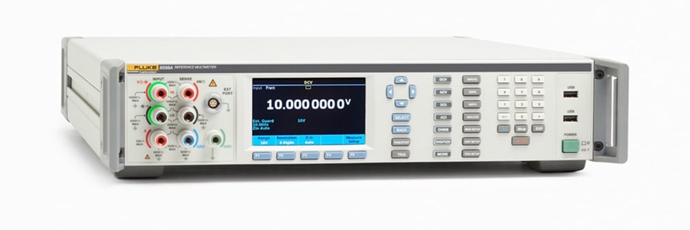
Verifying the capacitance function of the 8588A Reference Multimeter
Overview: This application note provides guidance to those wishing to verify the performance of the capacitance function of their 8588A Reference Multimeter. It describes the methodology, examines the measurement process, and describes some of the pitfalls that can occur.
As capacitance is derived from resistance, do you need to routinely verify the capacitance function at all? To answer this, first look at how the 8588A Reference Multimeter measures capacitance.
The 8588A measures capacitance using a DC discharge method that is fundamentally the same as the method used by handheld multimeters, but of a higher precision. In the case of the 8588A, the unknown capacitor is discharged until it is close to zero and then charged with a known constant current; this results in a negative going linear ramp that returns to zero at the end of each measurement cycle. The voltages close to the start and end of the ramp are measured and the capacitance calculated from C = I.ẟt/ẟv where C is the capacitance in Farads, I is the current in amps and v is the change in voltage over the time interval t.
The resistance function provides the constant current and voltage measurement capability and uses the same calibration constants for voltage and current that were determined during resistance adjustment, except for the 1 nF range, which is adjusted using an external reference capacitor due to the difficulty in characterizing the internal bias currents.
The capacitance function is also affected by timing errors. Internally the 8588A has one master clock, so these timing errors can be evaluated by measuring the frequency counter. The clock specification is 1 µHz/Hz, which is many orders better than the specification of the best capacitance range, so any timing errors can be effectively ignored.

From this description you can see that the performance of the 10 nF range and above could be monitored by evaluation of the appropriate resistance range. For many laboratories this may be the preferred option due to lack of suitably traceable standards. It is possible that the capacitance measurement could be affected by internal physical changes that would not show as a change in resistance; however, any change would have a greater impact on the lower capacitance ranges, which can be evaluated by comparison with readily available reference capacitors. Any change seen on these lower ranges would very quickly become insignificant as you go up range.
To answer the question; do you need to separately verify the capacitance function? Yes.
For the 1 nF range because its calibration is independent of the resistance range it uses, but optional for the 10 nF range and above. This is because the performance of these ranges can be monitored by observing the change in the appropriate resistance range given in Table 1.
| Capacitance range | Resistance range used |
| 1 nF | 100 MΩ, Lo I |
| 10 nF | 10 MΩ, Lo I |
| 100 nF | 1 MΩ, Lo I |
| 1 µF | 100 kΩ, Lo I |
| 10 µF | 10 kΩ |
| 100 µF | 1 kΩ |
| 1 mF to 100 mF | 100 Ω |
| 1 mF to 100 mF Lo | I 1 kΩ |
Using reference capacitors to verify the 8588A
The value of a typical reference capacitor commonly found in calibration laboratories changes with frequency and its configuration as a 2-terminal or 3-terminal device. The 8588A measures 2 terminal capacitance using the DC discharge method described above. We therefore need to know what the effective test frequency of the 8588A is, and the 2-terminal value of the reference capacitor at this frequency.
There is no direct equivalence between the ramped waveform of the 8588A and the frequency of a sine wave. However, a good approximation can be made by equating the slew rate of the ramp generated by the 8588A with the maximum slew rate of a sine wave using the relationship: v/s =2.π.f.Vpk where v/s is the slew rate in volts per second, f is the frequency in Hz and Vpk is the peak voltage. Table 2 lists the equivalent test frequencies determined using this relationship. Note that the frequency not only changes with range but also where the value lies within the range.
| 8588A range | Applied value % of range | Equivalent test frequency |
| 1 nF to 1 mF |
20% | 5.63 Hz |
| 100% | 1.13 Hz | |
| 200% | 0.56 Hz | |
| 10 mF |
20% | 0.68 Hz |
| 100% | 0.14 Hz | |
| 200% | 0.079 Hz | |
| 100 mF |
20% | 0.056 Hz |
| 50% | 0.023 Hz | |
| 100% | 0.011 Hz | |
| 1 mF Lo I |
20% | 0.56 Hz |
| 100% | 0.11 Hz | |
| 200% | 0.056 Hz | |
| 10 mF Lo I |
20% | 0.056 Hz |
| 100% | 0.011 Hz | |
| 200% | 0.005 6 Hz | |
| 100 mF Lo I |
20% | 0.005 6 Hz |
| 50% | 0.002 3 Hz | |
| 100% | 0.001 1 Hz |
It is unlikely that traceability will be available at the frequencies listed in the table, so the reference capacitor will need to be measured at multiple frequencies going as low as possible and the value extrapolated.
Fortunately, the 1 nF range is much simpler to verify. Air dielectric capacitors are available at this value which have negligible frequency dependence; this allows them to be characterized at 1 kHz and used at these low frequencies. The main consideration with these capacitors is that they are generally 3-terminal devices. Therefore, they will need to be modified by fitting a shorting connector to their low terminal that connects it to the case and then measured as a 2-terminal device.
An alternative approach
A slightly different approach is used at Fluke due to the volume of instruments going through the laboratory. We use a characterized 5522A Multi-Product Calibrator that has been characterized using an 8588A transfer standard and the previously described 1 nF capacitor.

The capacitance traceability for the transfer standard is derived from voltage, current, and time which has been validated against reference capacitors and a standalone measurement system which is also based on voltage, current, and time. This standalone measurement system has been used since the early 90’s by Fluke and is listed in the UKAS schedule of accreditation.
Keep learning
- Using precision digital multimeters in place of analog null meters for metrological applications
- Improved verification of a 55XX Series Multi-Product Calibrator with an 8588A Reference Multimeter
- Three Surprising Features of the 8588A Reference Multimeter
See related products
Get help
- ホーム
- 製品
- ご購入について
- ニュース
- トレーニングとイベント
- カタログ・資料
- サービスとサポート
- フルーク・キャリブレーション

